Bridging the gap
ROADS & HIGHWAYS

Bridging the gap

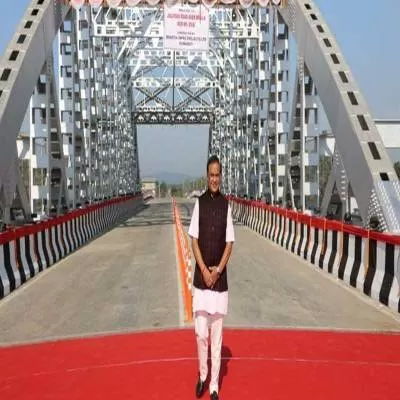
India's longest river bridge - Bridging the gap between Assam and Arunachal Pradesh<br /> India recently inaugurated its longest river bridge: The 9.15-km Dhola-Sadiya Bridge across river Lohit in upper Assam. This will open a route from northern Assam to Arunachal Pradesh, reducing the travel time between the two states from six hours to just one hour with the distance shrinking by 165 km. <p></p> <p><span style="font-weight: bold;">Crucial location</span><br /> While Dhola is on the southern side of river Lohit, Sadiya is on the north. The river provides a difficult barrier between South and North Assam. It flows in from China, similar to the Debang and Siang river systems. The three join together downstream of the present Dhola-Sadiya location, which is nearer the plains with less turbulence in the flow. While the perennial river is only 4-km wide, the bridge is 9.15-km long. When the river is in spate, it flows over a wide area. The 9.15-km stretch tries to cover this but there could be breaches during flooding. Apart from the bridge, the high embankments approaching from both ends constitute important components; together, they measure 28.5 km. There are also some minor bridges located in the approach embankments. </p> <p>The width of the bridge is 13.2 m; this includes a motor carriageway of 10.5 m with 0.9 m footpaths on either side. For the safety of vehicles, there are two crash barriers on either side.</p> <p> <span style="font-weight: bold;">Detailed civil design </span><br /> Four piles support each pier on the bridge. 'For the sake of foundation design, the bridge is divided into two: A proper river portion and floodplains,' explains Dr Ir Chandramohan PV, President-Technical, Navayuga Engineering Company. 'There are a total of 183 spans - 101 over the floodplains and 82 in the river portion. The basic span of the superstructure is 50 m. Bored cast-in-situ piles of 40 m length have been engaged for the foundation. As forces on the river portion are higher, the 324 piles in that reach are of 1,700-mm diameter, while the 412 in the floodplains are 1,500 mm.' These piles have been capped at the top. The caps in the river portion are 7.3 m sq and 2.55-m thick while the pile cap in the floodplains is 6.4 + 6.4 + 2.25 m. The bottom of the pile cap has been kept above high flood level to facilitate casting. 'The vertical load on the piles in the river portion came to 520 tonne,' adds Dr Chandramohan. 'The piles were load-tested for 1,300 tonne. Concrete of strength 40 MPa was used for the piles, while steel reinforcements for the pile had a strength of 500 MPa.' </p> <p>The structure has been designed as per IRC codes 112 and 6. The superstructure rests on elastomeric bearings that accommodate the rotation and translation movements of the girder. Piers transferring the load from the superstructure are at the centre on top of the pile cap. The superstructure is of a segmental box type, externally post-tensioned with high tensile strands. This avoids cables passing through the web of the box and reduces the thickness of the web and weight of the segment. Besides, the deck of the box is transversely post-tensioned to reduce thickness and weight. </p> <p>The post-tensioned concrete has a strength of 50 MPa while the high-tensile steel strands have a tensile strength of 1,860 MPa. </p> <p>For a span of 50 m, 15 segments have been used. 'The segmental box method is to precast the superstructure so it can be placed in position once construction reaches the bearing level,' says Dr Chandramohan. 'As the box could not be transported from the casting yard and placed in position, it was made in pieces. This is called segmental construction.' </p> <p> <span style="font-weight: bold;">Reducing structural load</span><br /> The bridge is located in seismic zone 5. Horizontal forces from seismic activity, breaking and temperature forces induce heavier bending moments in the pier and more so in the piles. The piles have been designed for this force. But this force has to be transferred successively from the superstructure down to the foundation. The final resistance of the seismic forces comes from the soil below. However, there should be effective load transfer at every connection, more so at the bearings. The superstructure simply rests on the bearings. It should be prevented from moving sideways or falling out of the pier. This is done by seismic arresters. These resist the seismic loads and transfer them to the pier. Vertical reinforcements have been used for transverse forces and stress bars for longitudinal forces.</p> <p> <span style="font-weight: bold;">Concrete connections</span><br /> In this bridge, piles, pile caps, the pier along with its cap and pedestals are made of reinforced concrete. But for the superstructure, post-tensioned concrete has been used. 'A pre-compression has been introduced by means of high tensile strands wherever tension is expected,' says Dr Chandramohan. 'These strands are passed through ducts. In an externally post-tensioned girder, these ducts are connected to the girder by means of deviator blocks and end blocks. </p> <p>The strands are tensed by means of post-tensioning jacks and anchored to the end blocks. This will induce compression in concrete. The bearings are made up of elastomers with steel plates embedded in the pads. Steel plates add stiffness to the flexible elastomers.' </p> <p> <span style="font-weight: bold;">Massive equipment </span><br /> For a bridge of this scale with 736 piles and 182 piers, the equipment requirements were also huge. Hydraulic rotary piling rigs were mobilised and a batching plant had to be set up. As the waters were wide and deep, it was decided to go step by step by doing the piling for a small reach and removing the filling thereafter. Excavators were used to fill up the river portions. 'Long-line casting was adopted for pre-casting the segments,' says Dr Chandramohan. 'The casting yard was like a gigantic factory. For the whole bridge, there were 2,745 segments. To cater to the amount of piers to be cast, a number of moulds were fabricated to ensure uninterrupted work. Moulds for the segments were another priority. Also, electric overhead cranes spanning the casting yard were required to move the segments. Transverse stressing equipment and strands with flat ducts were required before moving them and mobile cranes were utilised to stack them. </p> <p>The segments were initially launched in the floodplains through ground-supported erection. In the river portion, the segments were launched by a gantry. They were put on trailers and moved on the erected portion of the bridge to the back reach of the launching girder and erected in position after post-tensioning.'</p> <p> <span style="font-weight: bold;">Challenges in construction </span><br /> The sheer scale of the project was a challenge and the planning had to also take into account the reduced time owing to floods. </p> <p>As Dr Chandramohan says, 'The project required massive infrastructure and the floods were very damaging. On one occasion, we were able to just scramble out of the way a piling rig; a couple of cranes were, however lost. During one destructive flood, the approach embankment was cut. The casting yard was flooded for days, stopping work. In the face of all this, we were able to complete the project within five years. With a BOT tender on an annuity basis, design and construction have been done such that maintenance requirements are minimal.' </p> <p> <span style="font-weight: bold;">Kudos!</span></p> <p> <span style="font-weight: bold;">Project Details</span><br /> <span style="font-weight: bold;">Location:</span> Upper Assam<br /> <span style="font-weight: bold;">Completion:</span> May 2017<br /> <span style="font-weight: bold;">Length: </span>9,150 m<br /> <span style="font-weight: bold;">Foundation design and construction contractor:</span> Navayuga Engineering Company.<br /> <span style="font-weight: bold;">Tel: </span>040-2333 9990. <br /> <span style="font-weight: bold;">Website:</span> www.necltd.com<br /> <span style="font-weight: bold;">Superstructure and substructure design:</span> Precast Bridge Tech, Bangkok.<br /> <span style="font-weight: bold;">Contracting agency:</span> Navayuga Engineering Company.<br /> <br /> <span style="font-weight: bold;">- SERAPHINA D'SOUZA</span></p> <p><br /> Know of a landmark project? Write in at feedback@ConstructionWorld.in<br /> </p>

India's longest river bridge - Bridging the gap between Assam and Arunachal Pradesh<br /> India recently inaugurated its longest river bridge: The 9.15-km Dhola-Sadiya Bridge across river Lohit in upper Assam. This will open a route from northern Assam to Arunachal Pradesh, reducing the travel time between the two states from six hours to just one hour with the distance shrinking by 165 km. <p></p> <p><span style="font-weight: bold;">Crucial location</span><br /> While Dhola is on the southern side of river Lohit, Sadiya is on the north. The river provides a difficult barrier between South and North Assam. It flows in from China, similar to the Debang and Siang river systems. The three join together downstream of the present Dhola-Sadiya location, which is nearer the plains with less turbulence in the flow. While the perennial river is only 4-km wide, the bridge is 9.15-km long. When the river is in spate, it flows over a wide area. The 9.15-km stretch tries to cover this but there could be breaches during flooding. Apart from the bridge, the high embankments approaching from both ends constitute important components; together, they measure 28.5 km. There are also some minor bridges located in the approach embankments. </p> <p>The width of the bridge is 13.2 m; this includes a motor carriageway of 10.5 m with 0.9 m footpaths on either side. For the safety of vehicles, there are two crash barriers on either side.</p> <p> <span style="font-weight: bold;">Detailed civil design </span><br /> Four piles support each pier on the bridge. 'For the sake of foundation design, the bridge is divided into two: A proper river portion and floodplains,' explains Dr Ir Chandramohan PV, President-Technical, Navayuga Engineering Company. 'There are a total of 183 spans - 101 over the floodplains and 82 in the river portion. The basic span of the superstructure is 50 m. Bored cast-in-situ piles of 40 m length have been engaged for the foundation. As forces on the river portion are higher, the 324 piles in that reach are of 1,700-mm diameter, while the 412 in the floodplains are 1,500 mm.' These piles have been capped at the top. The caps in the river portion are 7.3 m sq and 2.55-m thick while the pile cap in the floodplains is 6.4 + 6.4 + 2.25 m. The bottom of the pile cap has been kept above high flood level to facilitate casting. 'The vertical load on the piles in the river portion came to 520 tonne,' adds Dr Chandramohan. 'The piles were load-tested for 1,300 tonne. Concrete of strength 40 MPa was used for the piles, while steel reinforcements for the pile had a strength of 500 MPa.' </p> <p>The structure has been designed as per IRC codes 112 and 6. The superstructure rests on elastomeric bearings that accommodate the rotation and translation movements of the girder. Piers transferring the load from the superstructure are at the centre on top of the pile cap. The superstructure is of a segmental box type, externally post-tensioned with high tensile strands. This avoids cables passing through the web of the box and reduces the thickness of the web and weight of the segment. Besides, the deck of the box is transversely post-tensioned to reduce thickness and weight. </p> <p>The post-tensioned concrete has a strength of 50 MPa while the high-tensile steel strands have a tensile strength of 1,860 MPa. </p> <p>For a span of 50 m, 15 segments have been used. 'The segmental box method is to precast the superstructure so it can be placed in position once construction reaches the bearing level,' says Dr Chandramohan. 'As the box could not be transported from the casting yard and placed in position, it was made in pieces. This is called segmental construction.' </p> <p> <span style="font-weight: bold;">Reducing structural load</span><br /> The bridge is located in seismic zone 5. Horizontal forces from seismic activity, breaking and temperature forces induce heavier bending moments in the pier and more so in the piles. The piles have been designed for this force. But this force has to be transferred successively from the superstructure down to the foundation. The final resistance of the seismic forces comes from the soil below. However, there should be effective load transfer at every connection, more so at the bearings. The superstructure simply rests on the bearings. It should be prevented from moving sideways or falling out of the pier. This is done by seismic arresters. These resist the seismic loads and transfer them to the pier. Vertical reinforcements have been used for transverse forces and stress bars for longitudinal forces.</p> <p> <span style="font-weight: bold;">Concrete connections</span><br /> In this bridge, piles, pile caps, the pier along with its cap and pedestals are made of reinforced concrete. But for the superstructure, post-tensioned concrete has been used. 'A pre-compression has been introduced by means of high tensile strands wherever tension is expected,' says Dr Chandramohan. 'These strands are passed through ducts. In an externally post-tensioned girder, these ducts are connected to the girder by means of deviator blocks and end blocks. </p> <p>The strands are tensed by means of post-tensioning jacks and anchored to the end blocks. This will induce compression in concrete. The bearings are made up of elastomers with steel plates embedded in the pads. Steel plates add stiffness to the flexible elastomers.' </p> <p> <span style="font-weight: bold;">Massive equipment </span><br /> For a bridge of this scale with 736 piles and 182 piers, the equipment requirements were also huge. Hydraulic rotary piling rigs were mobilised and a batching plant had to be set up. As the waters were wide and deep, it was decided to go step by step by doing the piling for a small reach and removing the filling thereafter. Excavators were used to fill up the river portions. 'Long-line casting was adopted for pre-casting the segments,' says Dr Chandramohan. 'The casting yard was like a gigantic factory. For the whole bridge, there were 2,745 segments. To cater to the amount of piers to be cast, a number of moulds were fabricated to ensure uninterrupted work. Moulds for the segments were another priority. Also, electric overhead cranes spanning the casting yard were required to move the segments. Transverse stressing equipment and strands with flat ducts were required before moving them and mobile cranes were utilised to stack them. </p> <p>The segments were initially launched in the floodplains through ground-supported erection. In the river portion, the segments were launched by a gantry. They were put on trailers and moved on the erected portion of the bridge to the back reach of the launching girder and erected in position after post-tensioning.'</p> <p> <span style="font-weight: bold;">Challenges in construction </span><br /> The sheer scale of the project was a challenge and the planning had to also take into account the reduced time owing to floods. </p> <p>As Dr Chandramohan says, 'The project required massive infrastructure and the floods were very damaging. On one occasion, we were able to just scramble out of the way a piling rig; a couple of cranes were, however lost. During one destructive flood, the approach embankment was cut. The casting yard was flooded for days, stopping work. In the face of all this, we were able to complete the project within five years. With a BOT tender on an annuity basis, design and construction have been done such that maintenance requirements are minimal.' </p> <p> <span style="font-weight: bold;">Kudos!</span></p> <p> <span style="font-weight: bold;">Project Details</span><br /> <span style="font-weight: bold;">Location:</span> Upper Assam<br /> <span style="font-weight: bold;">Completion:</span> May 2017<br /> <span style="font-weight: bold;">Length: </span>9,150 m<br /> <span style="font-weight: bold;">Foundation design and construction contractor:</span> Navayuga Engineering Company.<br /> <span style="font-weight: bold;">Tel: </span>040-2333 9990. <br /> <span style="font-weight: bold;">Website:</span> www.necltd.com<br /> <span style="font-weight: bold;">Superstructure and substructure design:</span> Precast Bridge Tech, Bangkok.<br /> <span style="font-weight: bold;">Contracting agency:</span> Navayuga Engineering Company.<br /> <br /> <span style="font-weight: bold;">- SERAPHINA D'SOUZA</span></p> <p><br /> Know of a landmark project? Write in at feedback@ConstructionWorld.in<br /> </p>
Related Stories

Gold Stories

Hi There!

Now get regular updates from CW Magazine on WhatsApp!

Click on link below, message us with a simple hi, and SAVE our number

You will have subscribed to our Construction News on Whatsapp! Enjoy

+91 81086 03000

Join us Telegram