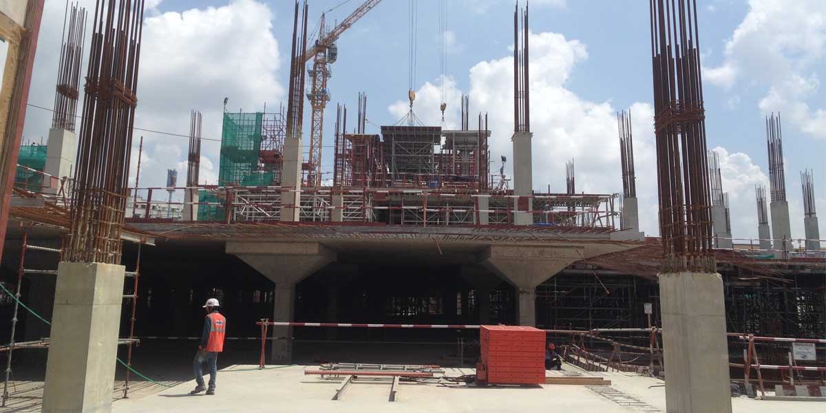
Using building material and resources conventionally falls short to meet the current demand of modern construction, let alone future demand. Coming to formwork, improvising for a better designed, robust, digitised and eco-friendly style is essential to make engineering sustainable, according to Sachin More, Head, Formwork, JMC Projects (I). “Systems needing fewer workers are speedier and more sophisticated. Fair finish is another buzz phrase and it symbolises improvised formwork that, when stripped away, leaves a product perfect in shape and size, with an aesthetic, homogenous, colour uniform surface, ready to be inaugurated, thus saving a lot of time that would otherwise be spent on finishing.”
The key takeaway?
Innovation is critical to ensure that formwork makes a desirable contribution to construction. Also, best-fit solutions are essential to push the adoption of formwork. Contractors need solutions appropriate for their projects. For instance, “formwork solutions for buildings of up to 10 floors can be much lighter than solutions for midrise and high-rise towers,” points out Sandeep Verma, Director, Formwork, Sharp Ply (India). Here, lighter also implies less expensive so better suited to the project and more likely to be adopted.
And Shanmugaraju K, Formwork Design Specialist, says, “Better solutions are arrived at by using available materials with better engineering and better coordination with all stakeholders.”
We agree!
Biggest table formwork ever to be used in India
Case 1
Project type: Building
Name: IKEA Retail Outlet
Location: Hyderabad
Contractor: Leighton India Contractor
Formwork system used: RMD Alshor Plus
Project description: The building has five floors – two basements for parking, a ground floor and two floors comprising a market hall, warehouse, showroom, restaurant, home delivery area and kindergarten with a gross built-up area of 94,334 sq m. The project consists of a slab plate of about 22,000 sq m with a 375-mm-thick slab at the maximum point of 5.5 m floor-to-floor height.
Reasons for selection: “We chose the RMD Alshor Plus aluminium shoring with a table system, marking the first time this system was being used for a building project in India,” says Jyoti Swaroop Chillar, Formwork Head, Signature Global. “The clear span (grid) between the huge columns was 8 m × 16 m. The construction schedule was so tight that no other system would have been able to fulfil this requirement. In fact, to be more productive, we got the provider to design a single table of 47 sq m weighing about 2.5 tonne, the biggest table formwork ever to be used in India. Four workers were sufficient to de-shutter and shift the system to the slab with the help of a hydraulic wheel trolley and crane C-hook for lifting. We achieved a six-day cycle (on average). RMD Alshor Plus has a load bearing capacity of 120 KN/leg, which gave us the liberty to design the big table formwork. Because of the very large area of each table, a lightweight system that can easily be lifted with tower cranes was essential. We believed that the lightweight system with minimal loose parts would reduce the cost and need for logistics and handling and storage, and help be more productive.”
Surmounting the challenges: “The project has huge columns of 1 m × 2 m dimension with a flair of 5.6 m × 2.8 m × 1.5 m depth,” continues Chillar. “Integrating the column formwork with the table formwork and achieving the desired cycle time was one of the biggest challenges. All available standard formwork systems for columns would have resulted in a heavyweight system. So, lightweight aluminium formwork column was predesigned. Just two workers could handle the system.”
Final statement: “Leighton laid emphasis on safety, followed by quality and productivity,” adds Chillar. “Every formwork system went through several peer checks for these factors before being finalised. This was a great learning for me.”
Case 2
Using system formwork alongside existing formwork Project type: Commercial building
Name: Kamdhenu 23 West
Location: Navi Mumbai
Contractor: Lakshmi Narayan Construction
Formwork system used: Variflex Formwork, Varieco Formwork
Reason for selection/surmounting the challenges: “Our customer had a huge inventory of conventional formwork so our designers utilised their available material with our slab formwork solution Variflex, comprising imported calibrated plywood and H20 beams, to cut their out-of-pocket expenditure,” says Sandeep Verma, Director - Formwork, Sharp Ply (India). “Once the contractor experienced the reduced cycle time, superior finish, the need for fewer workmen and the imperative to speed up work post-COVID, they came back to us for column, shear wall and lift core formwork solutions. Again, the challenge was their minimal budget and huge existing conventional inventory. We proposed Varieco Formwork and closely worked with the customer’s onsite planning team to evaluate the construction sequence. Jointly, we came up with a BOQ for their columns, shear wall and core wall such that no panels would remain unutilised on site, thus ensuring the maximum repetition of their formwork. We also deputed an experienced formwork instructor to train and guide the workers and site engineers.”
Final statement: “The Indian formwork and scaffolding market is still in an early growth stage where R&D and trials play a significant role,” continues Verma. “Contractors will not switch to system formwork leaving aside their existing stock of conventional formwork. They can be motivated to start using system formwork if the solution is economically priced and available on flexible payment terms and, most important, utilises as much as possible of their existing conventional formwork inventory and they are given the option to replace that with modern system formwork in a phased manner.”
Case 3
Formwork enabling fair finish surfacesProject type: Building
Name: Rural Electrification Corporation World Headquarters
Location: IFFCO Chowk, Gurgaon
Contractor: JMC Projects (I)
Formwork system used: Modular Wallform System (with H-beam + waller + 18 mm birch ply), Seamless Paper Formwork (for the round columns)
Project description: A commercial building including an auditorium
Reasons for selection: “Curves running along the horizontal and vertical sides of the structure were our biggest challenge, as these defined the construction methodology we adopted, the pour sequence and height of the formwork relative to the height of the structure,” says Sachin More, Head, Formwork, JMC Projects (I). “We chose H20 timber beam with a heavy duty waler system and 220 GSM film-faced double layer birch plywood of 18-mm thickness for the skin of the curvature shutters. Circular formwork for columns is not just seamless but has a mirror finish. We used shutters sized exactly to match the structural pattern and work sequence. For an impression-free surface, only the rear side of the plywood was used to avoid the ply branding impression. We engineered a predefined pattern of joints and holes for shuttering and fixing the accessories, with special cones for tie rods. For reverse screwing, we used an additional layer of 18-mm plywood strips. We used high-grade tie rods, PVC sleeves and locking arrangements. We used heavy-duty turn buckle (push pull) props for the alignment. For a seamless mirror finish, we used paper formwork, a first for India.”
Methodology: “We used a special platform to make the shutters and accurately arrange the H-beams,” continues More. “Chiselling the timber helped make curves of the perfect chord and shape. Where needed, an additional layer of packing timber helped achieve the exact radius and secondary plywood ribs were carefully screwed on top in perpendicular. To achieve the curved surface, the rear side of the plywood was grooved with linear pitches @ 50 mm c/c and screwed from the rear side to the secondary ply ribs. We used high-density sealing tapes at the joints to ensure no loss or leakage of slurry. High-capacity cranes assured easy handling. The fair finish surface was covered with flexi plywood because it suits practical applications with bends and curves. Masking tape and small nails helped joint the plywood.”
Final statement: “Engineering the smallest detail and highly skilled and specially trained manpower made this happen,” adds More. “There was no room for small mistakes, which could cause a loss. We are doing our next project at IIT Tirupati with fair finish technology.”
Case 4
Redesigning existing formwork
Project type: Residential building
Name: EWS Type-C (with/without shop cluster), part of a mass housing project
Location: Taloja, Navi MumbaiClient: L&T Construction’s Buildings and Factories
Formwork system used: Aluminium formwork
Reason for selection: “L&T has a huge quantity of aluminium formwork from earlier projects. They wanted to reuse this formwork as it had not yet exhausted its life (200-300 repetitions, based on different manufacturers),” shares Damini Pharande, Managing Director, HD Structures.
Overcoming the challenges: “We aimed at redesigning the existing system with minimal wastage and modification,” continues Pharande. “Essentially, we applied the old bill of quantities to suit the new tower, which was not a regular tower as it had offsets, window hoods, external grooves with different patterns and projected bands. For this, we studied the existing material and old formwork scheme drawings. To avoid modification of the panels, we reduced the non-standard panels.”
Methodology: “First, we finalised the shell drawing, which is a concrete layout, a combination of the architectural drawing and RCC drawing,” adds Pharande. “Then came the formwork modulation stage in which we placed the panels with respect to our loading calculations. Preparing the bill of quantities followed and thereafter the project was handed over.”
Case 5
Using conventional formwork for a complex infrastructure design
Project type: Transportation infrastructure
Name: Mumbai Coastal Road Project Package 2
Location: Worli Sea Face, Mumbai
Contractor: HCC-HDC (JV)
Formwork system used: A conventional formwork system with mild steel shuttering to cast the crown portion as a precast element and to erect the precast crown element on the top of the stem portion of the sea wall
Project description: 2,500-m sea wall along the coastline. The cross-section of the sea wall comprised three sections: the base, stem and crown. The height of the stem portion varied from 400 mm to 1,800 mm. The element above the stem portion was the crown. The depth of the crown was 900 mm uniform throughout. We opted for a precast crown element because of its geometry and the prevailing site conditions (the marine environment). Based on the variations/transitions in the base and stem portions, the entire stretch was divided into three types. Initially, clearance was received for the second and third types. Dimensional variations in terms of width and height of the base and stem portions pertaining to these types are shown below:
Reasons for selection: “We desired a safe and economic formwork solution to work with the materials available at site,” explains Shanmugaraju K, Formwork Design Specialist. “However, the varied dimensions of the elements of the structure, the progress of reclamation and the marine environmental conditions prompted the use of conventional shuttering materials, such as plywood, ISA angles, ISMC members, circular tubes, tie rods and turn buckles, as opposed to more expensive proprietary formwork systems.”
Overcoming the challenges: “The main challenge was the interface between the cast-in-situ elements with the top precast crown element,” continues Shanmugaraju. “Also, as it was not possible to provide formwork supporting arrangements on the sea side, the supporting arrangements were designed keeping in mind that the formwork shall be supported only from the land side.”
Methodology/approach: “In the second pour, easily removable box shutters were provided in the stem portion to create a void portion for stitch concrete,” adds Shanmugaraju. “Two 200-mm diameter pipe sleeves were provided throughout the depth of the precast segment for stitch concreting through which the void of the stem portion got filled with self-compacting stitch concrete. Considering the weight of one element, we chose 4 m (weight = 7.6 t) as the length of a precast element. The precast segments were placed on the stem and fixed with tie rods until the stitch concrete achieved its full strength.”